
Low voltage earthing systems are standardized under IEC 60364-3 and are classified into three main types: IT, TT, and TN. These systems are defined by how the neutral point of the power supply and the exposed conductive parts (e.g., equipment frames) are connected to earth. The naming convention uses two letters:
- First letter: Indicates the neutral point’s connection to earth.
- T: Directly earthed neutral.
- I: Unearthed or high impedance-earthed neutral.
- Second letter: Indicates the connection of exposed conductive parts to earth.
- T: Directly earthed exposed conductive parts.
- N: Exposed conductive parts connected to the neutral conductor.
Table of Contents
Low Voltage Earthing Systems: Definitions and Arrangements
1. IT System (Unearthed or Impedance-Earthed Neutral)

- Definition:
- The neutral is either unearthed or connected to earth via a high impedance (e.g., 1,700 Ω).
- Exposed conductive parts of the loads are interconnected and earthed, either collectively or individually if a group of loads is located far from others.
- Arrangements:
- An overvoltage limiter is mandatory between the MV/LV transformer neutral and earth (or a phase and earth if the neutral is inaccessible) to protect against overvoltages caused by faults or flashovers.
- Switching occurs upon a double fault (e.g., two simultaneous insulation faults), typically using phase-to-phase fault protective devices like circuit-breakers or fuses.
- If the short-circuit current is insufficient to trigger these devices (e.g., for distant loads), residual current devices (RCDs) are required.
- It is not recommended to distribute the neutral in IT systems to maintain system advantages and simplify protection.
- If a group of loads is individually earthed, it must be protected by an RCD.
2. TT System (Directly Earthed Neutral)
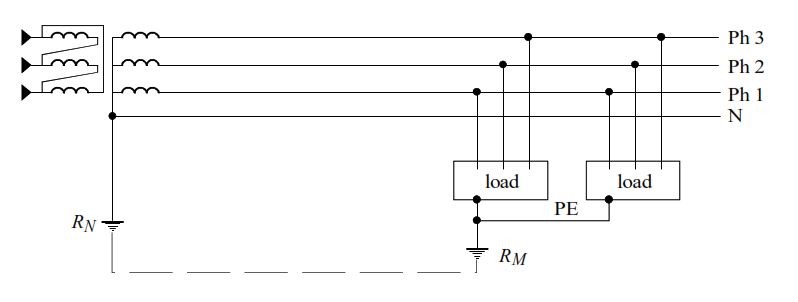
- Definition:
- The neutral is directly earthed.
- Exposed conductive parts are directly earthed, either interconnected as a group or individually if located far from others.
- Arrangements:
- RCDs are compulsory to protect against insulation faults.
- All exposed conductive parts protected by the same RCD must be connected to the same earth.
- The neutral earth and the exposed conductive parts’ earth may or may not be interconnected.
- The neutral may or may not be distributed, depending on the installation.
3. TN System (Neutral-Connected Exposed Conductive Parts)
- Definition:
- The neutral is directly earthed.
- Exposed conductive parts are connected to the neutral conductor.
- Arrangements: The TN system has two subtypes based on the neutral and protective conductor configuration:
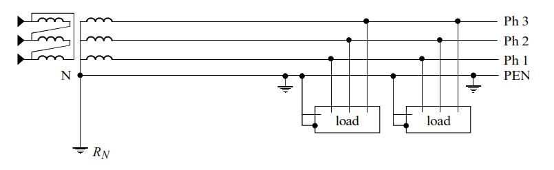
- TNC: The neutral and protective conductor are combined into a single conductor called the PEN (Protective Earth Neutral).
- Earthing connections must be evenly spaced along the PEN to prevent potential rises during faults.
- Restrictions apply: Not suitable for copper conductors < 10 mm², aluminum conductors < 16 mm², moveable trunkings, or downstream of a TNS system.
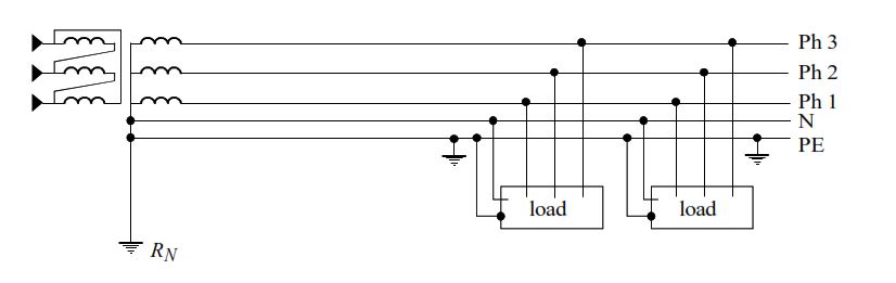
- TNS: The neutral and protective conductors are separate (N and PE conductors).
- Earthing connections must be evenly spaced along the PE conductor to maintain safety.
- Cannot be used upstream of a TNC system.
- Fault switching is achieved using overcurrent protective devices (e.g., circuit-breakers or fuses) for phase-to-phase faults.
Comparison of Different Earthing Systems in Low Voltage
Each earthing system has distinct operational characteristics, protection techniques, advantages, and disadvantages. Below is a comparison based on these aspects:
1. IT System (Unearthed or Impedance-Earthed Neutral)
- Operating Technique:
- Permanent insulation monitoring.
- Indication of the first insulation fault.
- Fault location and clearance are compulsory.
- Switching occurs only on a double fault.
- Protection Technique:
- Interconnection and earthing of exposed conductive parts.
- First fault monitored by a permanent insulation monitor.
- Switching on the second fault using overcurrent protective devices (e.g., circuit-breakers or fuses).
- Advantages:
- Provides the best service continuity as it does not trip on the first fault.
- Very low short-circuit current during an insulation fault.
- Disadvantages:
- Requires maintenance personnel to monitor the system.
- Needs a high level of network insulation, possibly requiring segmentation or insulating transformers for loads with high leakage currents.
- Overvoltage limiters are mandatory.
- Equipotential bonding of all exposed conductive parts is required; otherwise, RCDs must be used.
- Fault location can be challenging in large networks.
- Equipment must withstand higher voltages (phase-to-phase voltage) during faults.
- Tripping checks for double faults must be performed during design and commissioning.
- Neutral distribution is discouraged.
2. TT System (Directly Earthed Neutral)
- Operating Technique:
- Switching occurs on the first insulation fault.
- Protection Technique:
- Earthing of exposed conductive parts with compulsory RCDs (at least one at the installation head).
- All exposed conductive parts protected by the same RCD must share the same earth.
- Advantages:
- Simplest system to design, implement, monitor, and use.
- No permanent monitoring required; only periodic RCD tests are needed.
- RCDs with sensitivity ≤ 500 mA can prevent fire risks.
- Easy fault location.
- Small short-circuit current during an insulation fault.
- Disadvantages:
- Trips on the first fault, potentially interrupting service.
- Requires an RCD on each outgoing feeder for total selectivity.
- Special measures (e.g., insulating transformers or high-threshold RCDs) are needed for loads with high leakage currents to prevent spurious tripping.
3. TN System (TNC and TNS) (Neutral-Connected Exposed Conductive Parts)
- Operating Technique:
- Switching occurs on the first insulation fault.
- Protection Technique:
- Imperative interconnection and earthing of exposed conductive parts.
- Switching on the first fault via overcurrent protective devices (e.g., circuit-breakers or fuses).
- Advantages:
- TNC: Potentially lower installation costs (fewer conductors and switchgear poles).
- Uses overcurrent protective devices for protection against indirect contact.
- Disadvantages:
- Trips on the first fault, interrupting service.
- TNC: Requires fixed, rigid trunkings and has conductor size restrictions.
- Needs evenly placed earthing connections to maintain protective conductor potential.
- Tripping checks are required during design and commissioning.
- Protective conductors must run in the same trunkings as live conductors.
- Often requires additional equipotential bonding.
- TNC: Third and higher harmonics circulate in the PEN, increasing fire risk (not suitable for fire-risk areas).
- High short-circuit currents can damage equipment or cause electromagnetic disturbances.
Conclusion
- IT System: Ideal for applications prioritizing service continuity (e.g., critical infrastructure), but it demands careful maintenance and design to handle overvoltages and double faults.
- TT System: The simplest and safest option for general use, relying on RCDs, though it sacrifices continuity by tripping on the first fault.
- TN System: Efficient and cost-effective (especially TNC), but it produces higher fault currents and requires meticulous installation to ensure safety.
The choice of system depends on factors such as the need for service continuity, the type of loads, installation constraints, and maintenance capabilities. Each system balances safety, continuity, and complexity differently, making them suited to specific low voltage applications.