
Directional earth fault protection, identified by the ANSI code 67N, is a specialized protection function used in electrical networks with a compensated neutral, typically employing a Petersen coil earthing system.
This protection is designed to detect and isolate earth faults (single-phase-to-ground faults) in such networks by distinguishing the fault current in a faulty feeder from the capacitive currents in healthy feeders. Below, I’ll explain how this protection works, its key components, and its operational principles in a clear and structured manner.
Table of Contents
What is a Compensated Neutral Network?
A compensated neutral network is one where the neutral point of the power system (e.g., a transformer) is grounded through a Petersen coil, also known as a compensation coil. The Petersen coil is an inductor whose inductance is tuned to match the total capacitance of the network to ground.
In the event of a single-phase-to-earth fault:
- The capacitive current flows from the healthy phases to ground through the network’s capacitance.
- The Petersen coil provides an inductive current that ideally cancels out the capacitive current, reducing the fault current to a very small value.
However, in practice, perfect compensation is rare due to network variations or imperfect tuning, and the fault current may not be zero. To enable fault detection, a resistor is often added in parallel with the Petersen coil. This resistor introduces an active component (in-phase with the voltage) into the fault current, which is critical for the operation of the directional earth fault protection.
How Does Directional Earth Fault Protection (ANSI Code 67N) Work?
The directional earth fault protection (ANSI 67N) activates when two conditions are satisfied for a specified time delay:
- The active component of the residual current exceeds a setting threshold.
- The residual current is the vector sum of the three phase currents in a feeder, typically measured using a current transformer arrangement (e.g., a core-balance CT or the sum of phase CTs).
- The “active component” is the part of the residual current that is in phase with the residual voltage (more on this below).
- This active component is in the chosen detection direction.
- The detection direction is defined as the opposite direction to the residual voltage. The residual voltage is the vector sum of the three phase-to-neutral voltages, which appears during an earth fault due to the neutral point displacement.
When both conditions are met, the protection identifies the feeder as faulty and initiates a trip to isolate it.
Key Concepts: Residual Current and Voltage
To understand the protection’s operation, let’s define the key electrical quantities involved:
- Residual Current (I_{\text{rsd}}):
- For a faulty feeder (I_{\text{rsdf}}): This includes contributions from the fault current (via the Petersen coil and resistor) and the capacitive currents from all feeders.
- For a healthy feeder (I_{\text{rsdi}}): This is purely capacitive, resulting from the feeder’s capacitance to ground.
- Residual Voltage (V_{\text{rsd}}):
- During a solid phase-to-earth fault, the residual voltage is approximately V_{\text{rsd}} = -3 V_n, where V_n is the nominal phase-to-neutral voltage. This voltage serves as a reference for determining the direction of the residual current.
- Active Component:
- The active component of the residual current is its projection onto the line defined by the residual voltage. Mathematically, it’s the part of I_{\text{rsd}} that aligns with V_{\text{rsd}}.
Why Add a Resistor?
In a perfectly tuned compensated network (where the Petersen coil fully compensates the capacitive current), the fault current is purely reactive (90 degrees out of phase with the voltage) and lacks an active component. This makes it undetectable by standard overcurrent protection. By adding a high-value resistor in parallel with the Petersen coil:
- An active current component is introduced into the fault current.
- This active component is detectable and allows the directional protection to distinguish the faulty feeder.

The resistor limits the fault current to a few amps, balancing sensitivity and safety.
In a network with a Petersen coil earthing system, the value of the earth fault current (I_f) is given by: I_f = j \left( 3 C \omega - \frac{1}{L_N \omega} \right) V_n
Where:
- I_f: Earth fault current.
- C: Total network capacitance to ground.
- L_N: Inductance of the Petersen coil at the neutral.
- V_n: Nominal phase-to-neutral voltage.
- \omega: Angular frequency (e.g., 2\pi \times 50 \, \text{Hz} for a 50 Hz network).
Explanation:
The j indicates the current is purely reactive in an ideal case without a parallel resistor.
The term 3 C \omega V_n represents the capacitive current from the healthy phases through the network’s capacitance.
The term \frac{V_n}{L_N \omega} is the inductive current from the Petersen coil.
Distinguishing Faulty and Healthy Feeders
The protection relies on the difference in the residual current’s composition between faulty and healthy feeders:

Fault current I_{\text{f}} = I_{\ell} + I_{Cf} + I_{C1} + I_{C2} + I_{C3}
- Faulty Feeder Residual Current (I_{\text{rsdf}}):
Composed of:
- An active component due to the resistor (\frac{V_n}{R_N}).
- A reactive component due to the Petersen coil and network capacitance.
Expression:
I_{\text{rsdf}} = I_{\ell} + I_{C1} + I_{C2} + I_{C3}
Where:
- I_{\ell} = V_n \left( \frac{1}{R_N} + \frac{1}{j L_N \omega} \right) (current through the neutral impedance),
- I_{Ci} = 3 j C_i \omega V_n (capacitive current from feeder i),
- V_n is the phase-to-neutral voltage,
- R_N is the resistor,
- L_N is the inductance of the Petersen coil,
- C_i is the capacitance of feeder i,
- \omega is the angular frequency (e.g., 2\pi \times 50 \, \text{Hz}).
Simplified:
I_{\text{rsdf}} = \frac{V_n}{R_N} + j \left[ 3 (C_1 + C_2 + C_3) \omega - \frac{1}{L_N \omega} \right] V_n Since V_{\text{rsd}} = -3 V_n
for a solid fault:
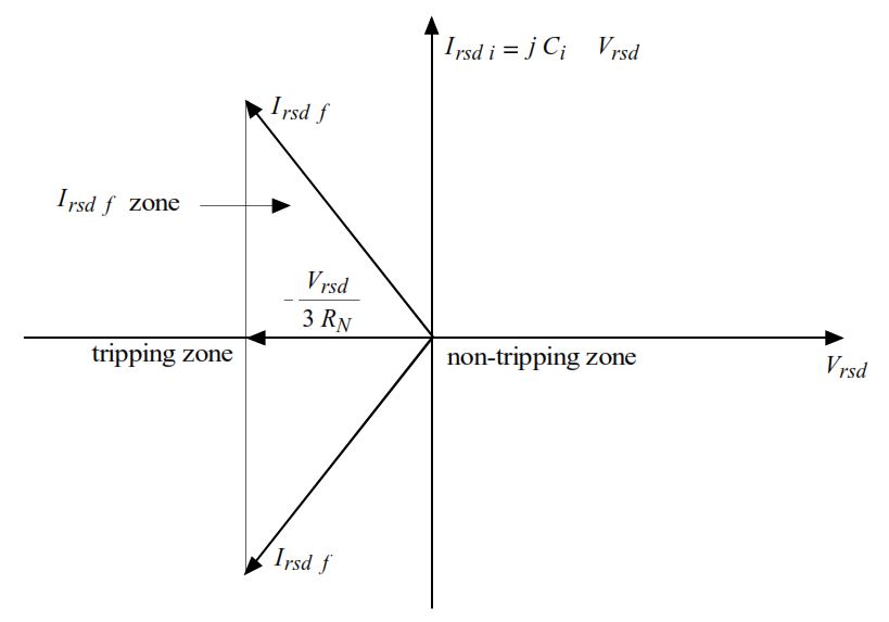
I_{\text{rsdf}} = -\frac{V_{\text{rsd}}}{3 R_N} - j \left[ (C_1 + C_2 + C_3) \omega - \frac{1}{3 L_N \omega} \right] V_{\text{rsd}}If perfectly tuned ((C_1 + C_2 + C_3) \omega = \frac{1}{3 L_N \omega}), the reactive part cancels out, leaving: I_{\text{p,rsdf}} = -\frac{V_{\text{rsd}}}{3 R_N} This is purely active and aligned with V_{\text{rsd}}.
2. Healthy Feeder Residual Current (I_{\text{rsdi}}):
Purely capacitive, as it’s due only to the feeder’s capacitance: I_{\text{rsdi}} = -I_{Ci} = -3 j C_i \omega V_n = j C_i \omega V_{\text{rsd}}
This current is 90 degrees out of phase with V_{\text{rsd}}, so its projection (active component) onto V_{\text{rsd}} is zero.
3. Phase Displacement:
Faulty feeder: I_{\text{rsdf}} has an active component in phase with V_{\text{rsd}} (or opposite, depending on convention), due to the resistor.
Healthy feeder: I_{\text{rsdi}} is perpendicular to V_{\text{rsd}}, with no active component.
Directional Detection
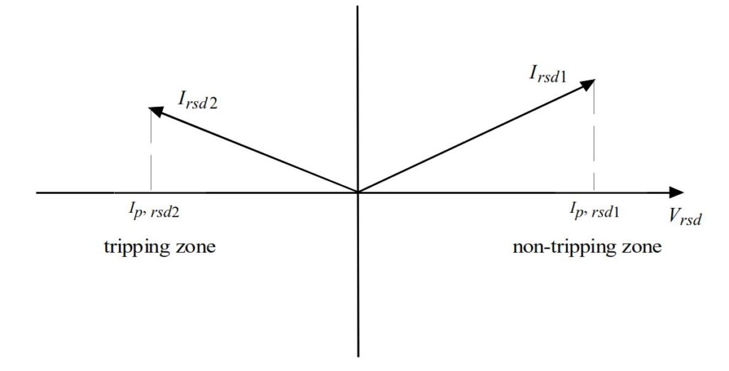
The protection calculates the active component by projecting I_{\text{rsd}} onto V_{\text{rsd}}:
- For the faulty feeder: The projection is non-zero (e.g., -\frac{V_{\text{rsd}}}{3 R_N}) and in the opposite direction to V_{\text{rsd}}, matching the detection criterion.
- For healthy feeders: The projection is zero, so the protection does not trip.
The tripping zone, as shown in typical diagrams (e.g., Figure 7-24), defines the region where I_{\text{rsd}} triggers the protection based on its magnitude and direction.
Practical Considerations
- Tuning Variations: Perfect tuning is rare due to changing network conditions (e.g., capacitance variations from feeder switching). The active component persists despite mistuning, ensuring detectability.
- Threshold Setting: The current threshold is set as low as possible (e.g., 1 A) to maximize sensitivity, while ensuring it exceeds the minimum detectable level of the protection device.
- Selectivity: The protection ensures only the faulty feeder trips, avoiding unnecessary outages on healthy feeders. A minimum feeder length (e.g., 670 m) may be required to guarantee sufficient capacitive current for selectivity.
- Why Directional? Non-directional protection might trip on healthy feeders due to capacitive currents, especially if mistuning causes I_{\text{rsdf}} and I_{\text{rsdi}} zones to overlap.
Conclusion
The directional earth fault protection (ANSI 67N) for compensated neutral networks operates by:
- Using a resistor in parallel with the Petersen coil to introduce an active component into the fault current.
- Measuring the residual current and voltage on each feeder.
- Detecting the active component of the residual current (projection onto the residual voltage) and verifying its direction (opposite to V_{\text{rsd}}).
- Tripping only the faulty feeder when the active component exceeds a threshold and aligns with the detection direction.
This ensures selective and reliable fault detection in compensated neutral networks, maintaining power supply continuity by isolating only the faulty feeder.