Welcome to this article dedicated to the Modbus communication protocol. In this comprehensive guide, we will explore in detail this widely used protocol in the field of industrial automation. Whether you are a student or an engineer, this introduction will provide you with the necessary basics to understand and implement the Modbus protocol.
The Modbus communication protocol is an open standard that enables the exchange of information between different electronic devices. It was developed in the 1970s by Modicon (now Schneider Electric) and has since become one of the most widespread protocols in the field of industrial automation.
In this enriched article, we cover the fundamental principles, frame structures, communication modes, variants (RTU, ASCII, TCP, UDP), master-slave architecture, function codes, data types, real-world application examples, advantages/disadvantages, advanced troubleshooting tips, and a conclusion on the future of Modbus. We also include a Modbus RTU frame decoder for better practical understanding.
Whether you simply want to learn more about how the Modbus protocol works or are considering using it in your own projects, this comprehensive guide will be a valuable resource to deepen your knowledge.
Ready to dive into the fascinating world of the Modbus communication protocol? Let’s get started without further ado!
Article Content
Modbus Communication Protocol: History
The Modbus communication protocol is one of the oldest and most used in the field of industrial automation. Its origins date back to the 1970s, when Modicon, a company specializing in programmable logic controllers, created this protocol to enable communication between its controllers and other equipment.
At the time, there were various proprietary communication protocols that made interoperability between equipment from different manufacturers difficult. Modbus came to solve this problem by offering an open and simple-to-implement protocol.
The success of the Modbus protocol lies in its simplicity and flexibility. It uses a master-slave architecture where a master device controls multiple slave devices. The messages exchanged between the master and slaves are simple and include addresses to identify the data to read or write.
Over the years, the Modbus protocol has evolved to adapt to new technologies and the growing needs of industry. Today, there are different variants of the Modbus protocol, such as Modbus RTU (using serial transmission) and Modbus TCP (using Ethernet).
Thanks to its ease of use and widespread adoption by industrial equipment manufacturers, the Modbus protocol continues to be widely used in various sectors such as energy, manufacturing production, and home automation.
In conclusion, the Modbus communication protocol has a rich history dating back to the 1970s. Its creation solved the interoperability problem between equipment from different manufacturers, and it continues to be used today thanks to its simplicity and flexibility.
How Does Modbus Work?
Modbus is a request-response protocol used in automation for communication between devices. It relies on a master-slave model: the master initiates requests (read/write data), and the slaves respond. This ensures a controlled unidirectional flow, avoiding collisions.
Communication uses a structured frame to transmit data. Each frame includes: the slave address (1 byte), the function code (1 byte indicating the action, such as reading registers), the data (variable), and error checking (CRC for RTU, LRC for ASCII). The media vary: serial (RS-232/485) for RTU/ASCII, or Ethernet for TCP/UDP.
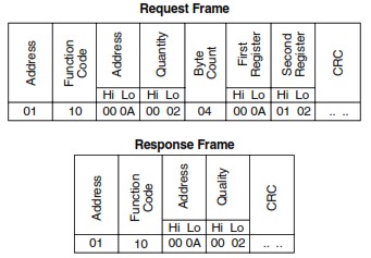
Modbus Frame Format
Here are the enriched formats for the main variants:
- Modbus RTU:
| Field | Size (bytes) | Description |
|---|---|---|
| Slave Address | 1 | Identifies the slave (1-247) |
| Function Code | 1 | Action (e.g., 0x03 for reading registers) |
| Data | Variable | Register address, count, values |
| CRC | 2 | Error checking (Cyclical Redundancy Check) |
FieldSize (bytes)DescriptionSlave Address1Identifies the slave (1-247)Function Code1Action (e.g., 0x03 for reading registers)DataVariableRegister address, count, valuesCRC2Error checking (Cyclical Redundancy Check)
- Modbus ASCII
| Field | Size (characters) | Description |
|---|---|---|
| Start Delimiter | 1 | ‘:’ (colon) |
| Slave Address | 2 | Identifies the slave in ASCII hex (e.g., ’01’ for address 1) |
| Function Code | 2 | Action in ASCII hex (e.g., ’03’ for reading registers) |
| Data | Variable (even number) | Register address, count, values in ASCII hex |
| LRC | 2 | Error checking (Longitudinal Redundancy Check) in ASCII hex |
| End Delimiter | 2 | CR LF (carriage return, line feed) |
- Modbus TCP (Ethernet):
| Field | Size (bytes) | Description |
|---|---|---|
| Transaction ID | 2 | Identifies the transaction (for matching requests/responses) |
| Protocol ID | 2 | Always 0000 for Modbus |
| Length | 2 | Length of the remaining message (Unit ID + PDU) |
| Unit ID | 1 | Identifies the slave (1-247, equivalent to slave address) |
| Function Code | 1 | Action (e.g., 0x03 for reading registers) |
| Data | Variable | Register address, count, values |
The master sends a request, the slave responds in typically 3-5 ms. If there’s an error, an exception code is returned (e.g., 0x01 for illegal function).
In summary, Modbus synchronizes industrial systems through simple and reliable frames, adapted to various networks.
Modbus Frame Format When a master device sends a request to a slave device, it typically asks it to perform a specific action, such as reading or writing registers. The slave device then responds with the requested results or an error code if the request could not be processed correctly.
The communication medium used by Modbus can vary depending on the system’s needs. It can be a RS-232/485 serial connection or a TCP/IP connection via Ethernet. These different media allow Modbus devices to communicate over various types of networks.
In summary, the Modbus protocol facilitates communication between electronic devices using a master/slave structure and a specific frame to transmit data. This allows industrial automation systems to operate efficiently and synchronously.
Modbus Protocol Communication Architecture
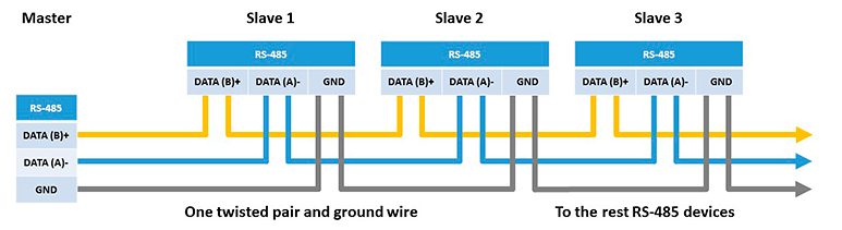
The Modbus architecture is key to its industrial integration. It supports various physical interfaces: RS-232 (point-to-point, short distances <15m), RS-485 (multipoint, up to 1200m, max 32 slaves without repeater), and Ethernet (TCP/UDP for unlimited distances, speeds >100 Mbps).
- Ethernet (TCP/IP): Enables IT/OT integration, with gateways to convert serial to Ethernet. Advantages: scalability, remote access via VPN.
- RS-232: Simple master-slave connection, ideal for local tests.
- RS-485: Multipoint bus, robust against noise, used in RTU for extended factories. Diagram: Master connected to a linear bus with 120Ω terminations.
In the case of using the RS232 serial interface, the Modbus protocol uses a point-to-point connection between the master (or controller) and the slaves (or peripherals). This interface is often used for applications requiring relatively short distances between equipment.
The RS485 version of Modbus allows multipoint communication, meaning a single master can communicate with multiple slaves on the same bus. This interface is often preferred when the distance between equipment is greater.
Finally, using Ethernet with the TCP/IP protocol offers additional flexibility in terms of distance and data transmission speed. It also enables communication with other computer networks, facilitating the integration of industrial systems into a broader environment.
Choosing the interface depends on constraints: distance, noise, speed. A good architecture ensures reliability and efficiency.
Types of Modbus Communication Protocols
When it comes to Modbus communication protocols, there are several types that are commonly used. These different types allow devices and systems to communicate with each other efficiently and reliably.
The first type is Modbus RTU (Remote Terminal Unit), which is a widely used serial protocol. It uses binary transmission over a serial line, making it suitable for long-distance communications.
Next, we have Modbus ASCII (American Standard Code for Information Interchange), which is also a serial protocol but uses text transmission. It is often used when compatibility with older systems is necessary.
The third type is Modbus TCP/IP (Transmission Control Protocol/Internet Protocol), which enables communication via Ethernet networks. This protocol offers advantages such as high speed and the possibility of bidirectional communication.
Finally, there is also Modbus UDP/IP (User Datagram Protocol/Internet Protocol), which is similar to Modbus TCP/IP but uses a connectionless protocol. This means it does not guarantee data delivery, but it offers lower latency and may be more suitable for certain specific applications.
It is important to choose the right type of protocol based on the specific needs of the system or device to connect. Each type has its own characteristics and advantages, so it is advisable to carefully evaluate the requirements before making a choice.
Modbus Master-Slave Communication
In a master-slave architecture, the master is responsible for initiating requests and managing data flow, while the slaves respond to the master’s requests by providing the requested information. This structure ensures efficient and reliable communication between the different components of a system.
A Modbus master can be either a SCADA system (Supervisory Control And Data Acquisition) that enables communication between a master and slaves, or a communication gateway that allows grouping a number of slaves.
To facilitate Modbus communication in more complex environments, such as those involving wireless links or direct connections, communication gateways can be used. These gateways act as intermediaries by converting the Modbus protocol to another protocol compatible with the existing system.
It is important to understand how the Modbus communication protocol works as well as the appropriate use of communication gateways to ensure smooth and reliable communication in a SCADA system.
Modbus Function Codes and Data Types
Modbus function codes are used to specify the type of action to perform during a Modbus request. Some commonly used function codes include reading data, writing data, writing multiple data, and reading/writing multiple data. Modbus data types include signed and unsigned integers, floating-point numbers, bits, character strings, etc.
| Code (Hex) | Name | Description |
|---|---|---|
| 0x01 | Read Coils | Read binary states (outputs) |
| 0x02 | Read Discrete Inputs | Read binary inputs |
| 0x03 | Read Holding Registers | Read read/write registers |
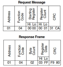
| 0x04 | Read Input Registers | Read read-only registers |
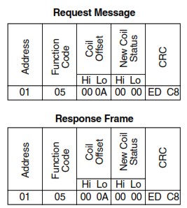
| 0x05 | Write Single Coil | Write a binary coil |
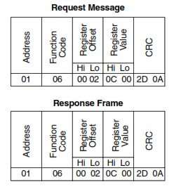
| 0x06 | Write Single Register | Write a register |
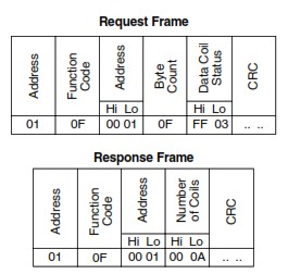
| 0x0F | Write Multiple Coils | Write multiple coils |
| 0x10 | Write Multiple Registers | Write multiple registers |
| 0x17 | Read/Write Multiple Registers | Read and write in one request |
Here is a brief explanation of the function codes and data types used by the Modbus communication protocol:
Modbus Function Codes
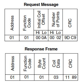
- 01 (0x01) – Read Coils: Used to read the status of binary outputs (coils) in a slave device.
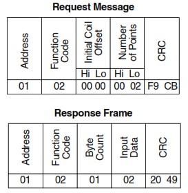
- 02 (0x02) – Read Discrete Inputs: Allows reading the status of binary inputs in a slave device.
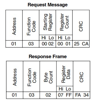
- 03 (0x03) – Read Holding Registers: Used to read the values of output registers in a slave device.
- 04 (0x04) – Read Input Registers: Used to read the values of input registers in a slave device.
- 05 (0x05) – Write Single Coil: Allows writing a binary value (0 or 1) to a specific coil in a slave device.
- 06 (0x06) – Write Single Register: Used to write a value to a specific output register in a slave device.
- 15 (0x0F) – Write Multiple Coils: Used to write multiple binary values to specific coils in a slave device.
- 16 (0x10) – Write Multiple Registers: Allows writing multiple values to specific output registers in a slave device.
Modbus Data Types
- Coils: Binary outputs that can be read or written.
- Discrete Inputs: Binary inputs that can only be read.
- Holding Registers: Registers that store read/write data.
- Input Registers: Registers that store read-only data.
The combination of Modbus function codes and data types enables efficient and targeted communication between master and slave devices in a Modbus network.
Modbus Communication Protocol: Application Examples
The Modbus communication protocol is widely used in various industrial applications. Among these applications are photovoltaic power plants, water distribution systems, and industry in general.
In the case of photovoltaic power plants, the Modbus protocol allows collecting and transmitting data such as energy production, solar panel temperature, or system status. This enables operators to monitor and control their installation remotely effectively.
In the field of water distribution systems, the Modbus protocol is used for supervising and controlling pumps, valves, and other equipment. It facilitates communication between these different components, allowing optimized management of the hydraulic network.
Industry in general also benefits from the Modbus protocol for its various applications. Whether for machine monitoring, process automation, or real-time data collection, this protocol offers a reliable and flexible solution.
In summary, the Modbus protocol finds its place in a wide range of applications from photovoltaic power plants to water distribution systems and industry. Its use enables better management and more precise control of the different systems involved.
Advantages and Disadvantages of Modbus
The Modbus communication protocol is widely used in industrial automation systems for transmitting data between different devices. However, it has both advantages and disadvantages that are important to consider.
One of the main advantages of Modbus is its simplicity. It uses a simple data structure and a limited set of instructions, which makes it easy to implement and understand. Additionally, it can be used on different physical media such as RS-485, Ethernet, or even the TCP/IP protocol.
Another major advantage is its compatibility with a wide range of industrial equipment. Modbus has been widely adopted by manufacturers of devices such as sensors, actuators, and programmable controllers, which facilitates the integration of different components in an automated system.
However, Modbus also has some disadvantages. First, it does not natively support data security. This means that if you use Modbus in an environment where information confidentiality is paramount, you will need to implement additional measures to protect your data.
Additionally, Modbus is not suitable for applications requiring high bandwidth or low latency. Its transmission speed is relatively slow compared to some other more modern protocols like Ethernet/IP or Profibus.
In conclusion, the choice to use the Modbus protocol will depend on the specific needs of the automated system. It offers simplicity and extensive compatibility, but it may not be suitable for all applications due to its limitations in terms of security and performance.
Troubleshooting Tips for Modbus
When it comes to troubleshooting issues related to the Modbus communication protocol, it is important to know the best practices for effectively resolving link and parameter problems.
First, check communication parameters such as transmission speed and parity settings. Ensure they are correctly configured to match the requirements of the Modbus device you are using. Errors in these parameters can lead to communication issues.
Next, use diagnostic tools such as protocol analyzers to monitor Modbus traffic. These tools allow you to analyze in detail the messages exchanged between devices and identify errors or anomalies in the communication.
The following table summarizes the most important exception codes that can be returned.
| Code | Meaning | Description |
|---|---|---|
| 01 | Illegal Function | The requested function is not supported |
| 02 | Illegal Data Address | The requested data address is not supported |
| 03 | Illegal Data Value | The specified data value is not supported |
| 04 | Failure in Associated Device | The slave did not respond to a message |
| 05 | Acknowledge | The slave is processing the command. |
| 06 | Busy, Rejected Message | The slave is busy. |
If you encounter specific issues with a Modbus device or application, consult the manufacturer’s documentation for specific troubleshooting advice. They can provide valuable information on optimal configuration and common problems encountered with their products.
Finally, also ensure that your cables and physical connections are in good condition. Damaged or poorly connected cables can lead to poor communication between devices.
By following these tips and using diagnostic tools judiciously, you will be able to quickly and effectively identify and resolve issues related to the Modbus protocol.
Conclusion
It is essential to consider the evolution of the Modbus protocol and compare it to other communication protocols. While Modbus has been widely used in industry for decades, it is important to ask whether it remains relevant in the era of emerging technologies.
Comparing it to other protocols can help us understand the advantages and disadvantages of Modbus compared to available alternatives. This can also give us indications about the direction the future of Modbus will take.
It is possible that Modbus will continue to be used in certain specific contexts where its simplicity and reliability are major assets. However, it is also possible that it will be gradually replaced by more advanced protocols offering greater flexibility, better security, or easier integration with other technologies.
It is therefore essential for engineers and professionals in the field to stay informed about the evolutions of the Modbus protocol as well as other options available on the market. This knowledge will enable them to make informed decisions about the future use of Modbus or the transition to other protocols based on the specific needs of their projects.
Modbus RTU Frame Decoder Discover
Our free online Modbus RTU/TCP frame encoder/decoder on our website. Simply enter your hexadecimal frame for instant encoding/decoding: slave address, function code, detailed data with register addresses, and CRC verification. Ideal tool for automation engineers, IoT developers, and industrial protocol enthusiasts. Easy, fast, and no installation required!
Pingback: Modbus RTU vs Modbus TCP: Key Differences, Advantages & Use Cases